- Home
- GPS & RF Equipment
- Line Amplifiers
- LA20FPDC-S
Product Description
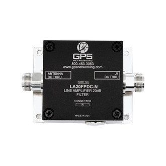
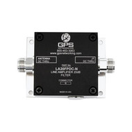
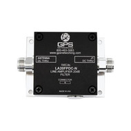
The LA20FPDC GPS Filtered Line Amplifier is a one input, one output device with a 20dB min. gain block and L1/L2 filtering. The frequency response covers both GPS L1 & L2 bands. In the standard configuration, the RF output (J1) passes DC from the connected GPS receiver through the amplifier to the antenna, allowing the GPS receiver to power both the antenna and the amp.
Electrical Specifications, TA = 25° C
| Parameter |
| Conditions |
| Min | Typ | Max |
| Units | ||
| Pass Band: L1 |
| Ant – J1 |
| 1.550 | 1.585 | 1.620 |
| GHz | ||
| Pass Band: L2 |
| Ant – J1 |
| 1.200 | 1.227 | 1.260 |
| GHz | ||
| In/Out Imped. |
| Ant, J1 |
|
| 50 |
|
| Ω | ||
| Gain |
| Ant – J1, L1 & L2 Passbands | 23.5 | 25 | 26.5 |
| dB | |||
| Input SWR |
| J1 - 50Ω, L1 & L2 Passbands |
|
| 2.0:1 |
| - |
| ||
| Output SWR |
| Ant - 50Ω |
|
|
| 1.6:1 |
| - |
| |
| Noise Figure |
| Ant – J1 |
|
| 5.9 |
|
| dB | ||
| Passband Ripple |
| Ant – J1, L1 & L2 Passbands |
| 1 | 2 |
| dB | |||
| Stopband Rej: L1 |
| 1595 +/- 200MHz, Relative to the passband | 22 |
|
|
| dB | |||
| Stopband Rej: L2 |
| 1241 +/- 150MHz | 30 |
|
|
| dB | |||
| Gain Flatness |
| [L1-L2] Input – Output |
| 1.0 | 2.0 |
| dB | |||
| Group delay Ripple: |
| τd,max - τd,min :Ant – J1, Across L1 Passband |
|
| 2 |
| ns | |||
| L1 |
|
|
|
|
|
|
|
|
|
|
| Group delay Ripple: |
| τd,max - τd,min :Ant – J1, Across L2 Passband |
|
| 3 |
| ns | |||
| L2 |
|
|
|
|
|
|
|
|
|
|
| Req. DC Input V. |
| Non-Network Configuration, DC Input on J1 | 4.0 |
| 15 |
| Vdc | |||
| Current (1) |
| Amplifier Current Draw, All ports - 50Ω |
|
| 30 |
| mA | |||
| (1) Current draw on | J1 port in the non-networked configuration. |
Downloads
| File | Type |
| LA20FPDC-specsheet-2015.pdf | Specsheet |
 Loading... Please wait...
