- Home
- GPS & RF Equipment
- Splitters
- ALDCBS1X4
Product Description
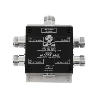
The ALDCBS1X4 "Amplified Loaded DC Blocked Splitter 1X4" GPS Splitter is an active one input, four output RF splitter that splits signals from 1.1 GHz to 1.7 GHz. This equipment is designed to amplify and split signals within the L-band to provide multiple devices with the signal from a single antenna.
In the standard configuration, the J1 port will pass DC voltage from a connected device and pass this power to the antenna or other devices upline from the splitter via the antenna port. The other ports (J2-J4) are DC blocked and loaded with 200Ω resistors to simulate antenna current draw which prevents antenna alarm faults. Custom gain configuration, DC configuration, and connector configuration are available upon request.
Electrical Specifications, TA = 25°C
|
Parameter |
Conditions |
Min |
Typ. |
Max |
Units |
|
Freq. Range |
Antenna – Any Output, Unused Outputs - 50Ω |
1.1 |
|
1.7 |
GHz |
|
In/Out Imped. |
Antenna, J1, J2, J3, J4 |
|
50 |
|
Ω |
|
Gain |
Normal Configuration, Antenna–Any Output |
17.0 |
18.5 |
20.0 |
dB |
|
Input SWR |
All ports - 50Ω |
|
|
2.0:1 |
- |
|
Output SWR |
Normal Configuration , All ports - 50Ω |
|
|
1.8:1 |
- |
|
Noise Figure |
Normal Config., Ant – Any Output, Unused Outputs - 50Ω |
|
4.2 |
4.5 |
dB |
|
Gain Flatness |
| L1 – L2 | ; Ant – Any Output, Unused Outputs - 50Ω |
|
0.5 |
1.5 |
dB |
|
Amplitude Balance |
| J1 – J4 | ; Ant – Any Output, Unused Outputs - 50Ω |
|
|
0.5 |
dB |
|
Phase Balance |
Phase (J1 – J4) ; Ant – Any Output, Unused Outputs - 50Ω |
|
|
1.0 |
deg |
|
Isolation |
Normal Config., Adjacent Ports, Ant - 50Ω (see plots) |
15 |
|
|
dB |
|
Group delay |
τd,max - τd,min :Antenna – J1, J2. J3, J4 -50Ω |
|
|
1 |
ns |
|
Flatness |
|
|
|
|
|
|
Req. DC Input V. |
Non-Network Configuration, DC Input on J1 |
3.6 |
|
15 |
Vdc |
|
Pı dB |
Output Power @ 1dB Gain Compression (f = 1.5GHz) |
|
-14 |
|
dBm |
|
Current Draw (1) |
Amplifier Current Draw, All ports - 50Ω |
|
|
15 |
mA |
Downloads
| File | Type | Description |
| ALDCBS1X4-SpecSheet2015.pdf | Spec Sheet | ALDCBC1X4 GPS Splitter Spec Sheet |
 Loading... Please wait...


