 Loading... Please wait...
- Home
- GPS & RF Equipment
- Splitters
- LDCBS1X2


Product Description
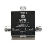
The LDCBS1X2 GPS Splitter is a one input, two output device based on the Wilkinson splitter design. The frequency response covers the GPS L1 & L2 bands with excellent gain flatness. In the normal configuration, one of the splitter RF outputs (J1) passes DC from the connected GPS receiver through the splitter to the antenna. The other RF output (J2) is DC loaded with a 200Ω resistor to block the DC voltage and to simulate the antenna current draw to prevent false antenna fault detection.
Electrical Specifications, TA = 25°C
|
Parameter |
|
Conditions |
Min |
Typ |
Max |
Units |
|||
|
Freq. Range |
|
Ant – Any Output, Unused Outputs - 50Ω |
1.1 |
|
1.7 |
GHz |
|||
|
Input/Output |
|
Ant, J1, J2 |
|
|
|
50 |
|
Ω |
|
|
Impedance |
|
|
|
|
|
|
|
|
|
|
Input SWR |
|
All ports - 50Ω |
|
|
2.0:1 |
- |
|||
|
Output SWR |
|
All ports - 50Ω |
|
|
1.5:1 |
- |
|||
|
Insertion Loss |
|
Ant – Any Output, Unused Outputs - 50Ω |
-3.6 |
-4.8 |
-6.0 |
dB |
|||
|
Gain Flatness |
|
| J1 - J2 | ; Ant – Any Output, Unused Outputs - 50Ω |
|
|
1.0 |
dB |
|||
|
Amplitude Balance |
|
| J1 – J2 | ; Ant – Any Output, Unused Outputs - 50Ω |
|
|
1.0 |
dB |
|||
|
Phase Balance |
|
Phase (J1 – J2) ; Ant – Any Output, Unused Outputs - 50Ω |
|
|
1.0 |
deg |
|||
|
Isolation |
|
Opposite Ports: Ant - 50Ω |
|
|
|
dB |
|||
|
|
|
|
|
|
|
|
|
|
|
|
Group delay |
|
τd,max - τd,min :Ant – J1 – J2- 50Ω; Ant – J2, J1 - 50Ω |
|
|
1 |
ns |
|||
Downloads
| File | Type | Description |
| LDCBS1X2-SpecSheet2015.pdf | Spec Sheet | LDCBC1X2 GPS Splitter Spec Sheet |
Find Similar Products by Category
Related Products
-
 ALDCBS1X2 US$399.00